
Design, planning and structural calculation:
Prof. Dr. Robert Off, Nadine Defee, Henning Dürr
Production:
Stegmaier Textile Solutions, Schemmerberg
Installation:
IMS Team, Lenz & Mundt Concrete Spraying, Brandenburg
Research:
IMS/Anhalt University Dessau, Gerry D'Anza, Wolfgang Warisch, Kristian Toureau, Henry Foltin, Stephanie Hofmann, Rabson Bota
The basic idea and research roadmap
Our overall goal was to use mechanically pre-stressed fabric structures, on behalf of formal approach and structural behavior and spray them with concrete.
Beside the research of the material technology, an important structural question was how to activate the pretension within the membrane to optimize the load bearing behavior of the overall composite structure. Starting point was the evaluation of the material properties to get an in-depth understanding of each material component. Different cements and strength classes, additives and maximum grain size categories were evaluated. With compression tests on cubical specimen, splitting tensile strength on cylindrical specimen and three-point-flexural-tension tests on prismatic specimen, we surveyed the compressive stresses and ductility of the concrete.

Second step was the evaluation of the fabric material. Beside the physical parameters, the main focus was on the chemical resistances (NaOH, H2SO4, Paraffin, NaCl, MgSO4 and K2CO3). The applicability of the different yarn materials, coating material as well as the size of the mesh openings and the weaving styles had to be assessed. Beside the technical values the properties concerning the processing and workability of the materials were of high interest. With the same testing program as for the individual materials we surveyed the composite behavior. In this stage of the research we took the influence of the level of pre-stress in the membrane layer (uniaxial as well as biaxial) into consideration. Special specimens were developed and the testing rigs had to be modified. With the three-point-flexural-tension testing we succeeded to record the characteristic material curve which was used to setup a model in a FEM Software.
Simultaneously to the investigation of the laboratory specimen, we executed spraying trials within “real” conditions to adjust the parameters (type of spraying, pressure, water-cement- ratio, distance and angle of the gun nozzle to the membrane) of the spraying process. From these trials we retrieved numerous samples and identified a big difference in the values between the “handmade” laboratory specimen and the sprayed specimen. Due to the parameters of the spraying process and the so called “Ruckprall” (the bouncing back of particles when they hit a surface) the applied concrete mixture differs from the initial mixture that is provided by the producer and was used for the lab-specimen.
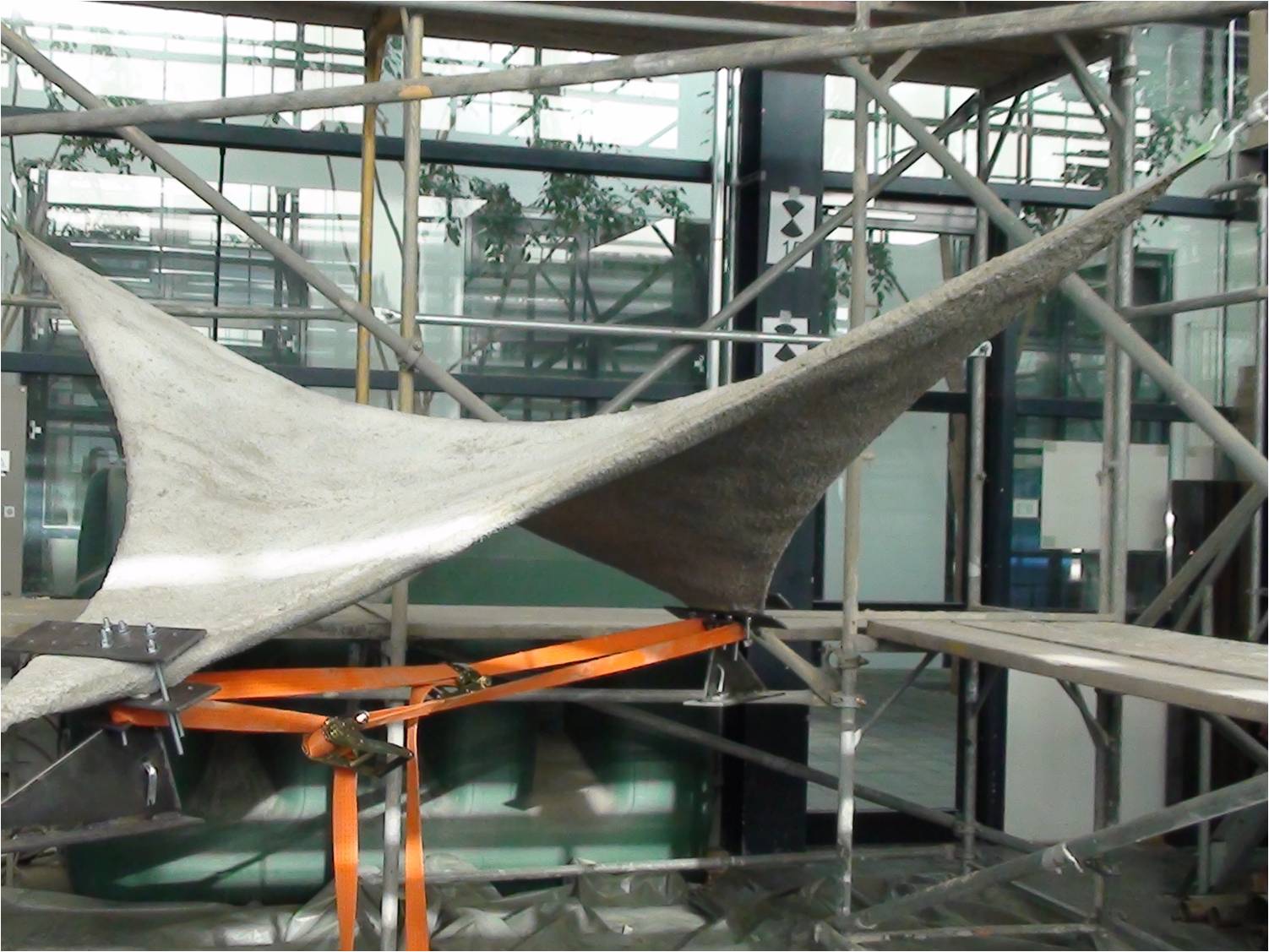
With a sail setup we started the evaluation of the findings from the material testing. The elaboration of the spraying process, the construction details and the overall structural behavior was the focus in this stage of the research. For simplification reason our first structure was a 4 point sail with cable edges (3m x 3m).
3d scans of the upper and lower side of the sail structure revealed the structure´s property to move and the insufficient level of pre-stress in the membrane caused a kind of ponding, hence a very uneven thickness of the sprayed concrete layer could be noticed.
In close collaboration with the Institute of Geoinformation and Surveying a very detailed deformation analysis was executed. Results and the applicability of the photogrammetric versus the 3d scanning survey during static and dynamic load tests were evaluated.
This first large scale attempt was very fruitful in detecting the real problems of the spraying process and helped to improve the design of the structural details.
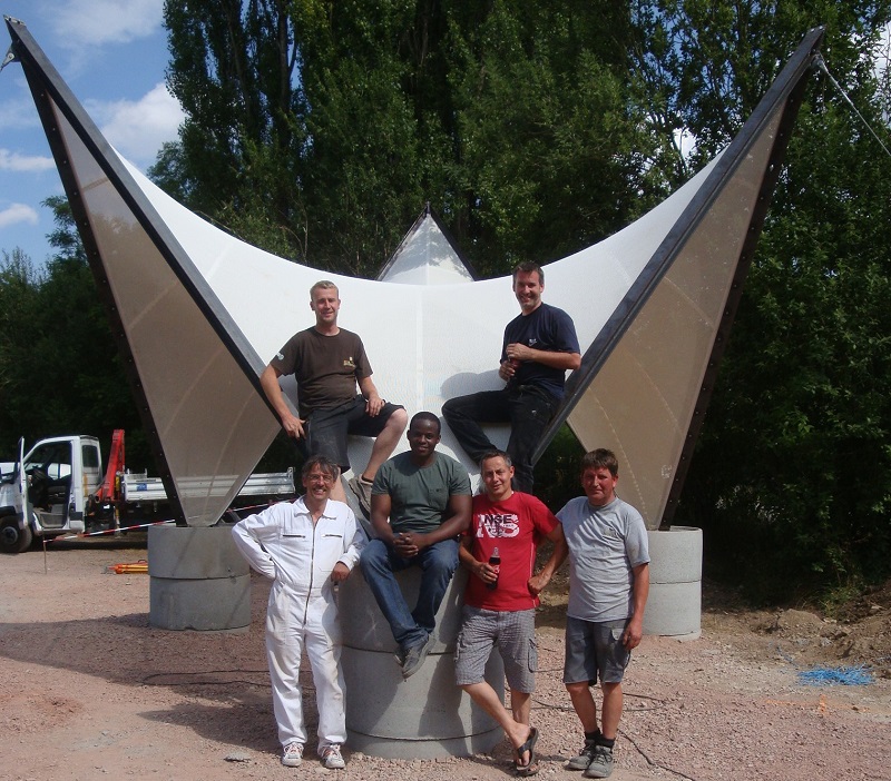
Prototype - planning, erection and monitoring
With the realization of the final prototype we wanted to gather more detailed knowledge while getting as close as possible to a real building situation. Curvature, usability, cost, testing facilities (also for the long-term behavior) were taken into account for the design task.
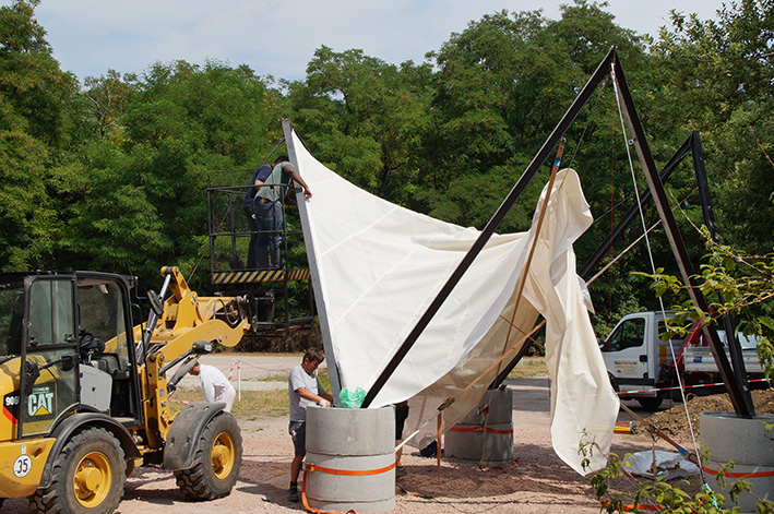
The geometry of the prototype is described by an anticlastic surface between 3 high points and three low points with rigid edges and ridgelines in the surface. It is 4.5m in height and 6.2m (at the highpoints) in diameter, and consists of the following building components:
- three steel A-frames (plus foundations) from HEA beams,
- three stay cables (plus foundations) with tensioning fittings,
- three ridge cables meeting in the central point of the surface.
The steel frames were connected to the foundations with hinged supports to allow movement for mounting and pre-stressing and for measuring the cable forces. In the axis of each stay cable we implemented two units for tensioning as well as a load cell to control, define and monitor the cable forces. From the preliminary large scale tests and the material survey we could develop a catalogue of specifications and hence decided for a steel fibre reinforced shotcrete and an open mesh fabric.
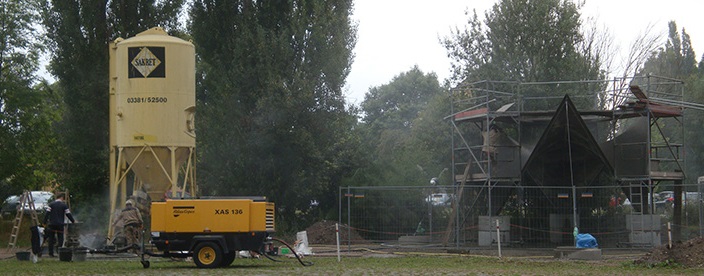
For a future application we decided to apply the concrete in more than one step. For large scale projects a first thin layer should give the structure enough stiffness to allow craftsmen walking on the structure for the following application steps. The second layer should guarantee the end rigidity of the concrete shell. The third and last layer was intended only for the final surface appearance. A smoothing treatment by hand was executed to seal the surface and prevent water and dirt from sticking on the surface. For an optimal bonding and adhesion of the shotcrete layers each layer was sandblasted before the next spraying application.
Loose grain material was removed and cracks were “opened”.
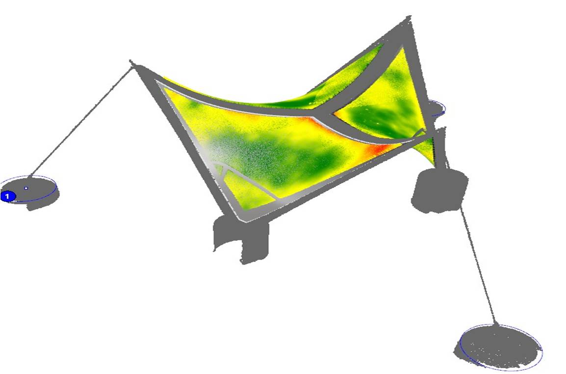
During the building process we executed various 3d scans to evaluate the geometry and tested how well the digital model and realized structure matched. Specimen from the onsite spraying were taken to the lab and compared to the assumed values. Cable forces were constantly monitored and adjusted according to the specifications.
The structural behavior was observed during mounting of the fabric structure, spraying and hardening process of the concrete. The verification of the various results and the merging of all parameters was challenging but also very promising. The comparison between the digital model and the real prototype gave various surprising findings and a holistic knowledge of the structures properties and behavior.
One key issue when applying the shotcrete was to guarantee an even distribution of the sprayed concrete. The geometry of the edge beams helped to define the layer thickness at least close to the edges. The thickness in the inner surface areas had to be monitored and manually adjusted by the skilled craftsman.
By matching scans from the upper and the lower surfaces and processing them, we could evaluate the variation of the layer thickness. Even though the specifications were held, a perspective for future structures could be to adapt and optimize the control of the layer thickness.
Prototype testing

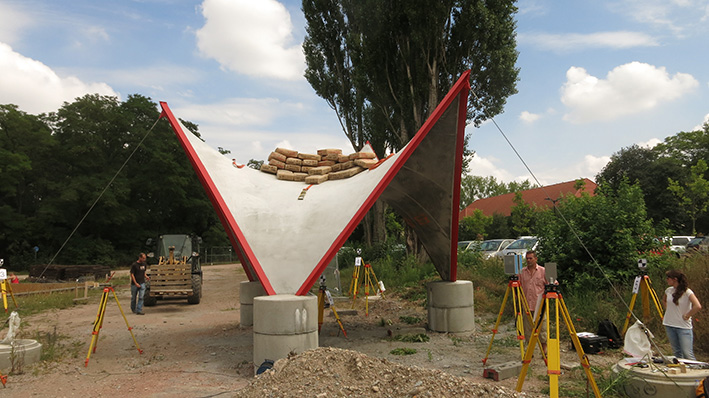
The last steps for a comprehensive under-standing and evaluation of the real shell structure behavior were the execution of the load test of the finalized membrane shell. In various load increments (750kg-1250kg) and different load cases we gathered the missing data.
On the one hand we distributed the load evenly on the shell surface in the center and most flat area. Secondly we put the load unsymmetrically on only one sector. On the third hand we simulated a pointload (675kg).
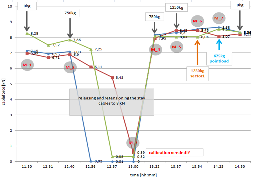
Simultaneously we monitored and evaluated the cable forces as well as the deflection for each load case.
Extracting specimen from the shell and executing laboratory tests (3-point-flexural tests) and comparing to the values of the reference object (unstressed, no fabric mesh layer). Characteristic material line (bending stresses) .
Perspective and Patent
Further efforts to establish a new and continuative research project are in progress.
A master thesis by Pedro Munoz (US representative of the IMS) is dealing with different shell geometries and is proceeding with additional and further research questions. Here the position of the fabric layer – periphery/neutral fibre will be investigated. In this field of interest the bonding of the composite as well as the material choice could be improved.
From the tests it seems that the level of biaxial prestress matters. Hence the system should be investigated with this focal point.
Another focus of refinement is the optimization of the monitoring of the deflection. Here the scanning procedure has to be refined or the method has to be changed to a photogrammetric approach. An alternative but time and cost consuming method could be to use strain gauges that are directly applied to the concrete shell.
Beside the present and future research efforts the system of prestressed membrane sprayed with concrete is about to be filed for patent.